A circular slide rule of outer diameter 240mm, an inner circle of diameter 210 mm and a radial arm of width 40mm. A slider, with a horizontal cross-wire, slides on the radial arm. A central metal rivet holds the individual sections together and allows the radial arm and inner circle to rotate independently of the outer circle. The two circles are made of a white celluloid material and the radial arm and slider are transparent acrylic. The rear side of the calculator contains detailed instructions as to the use of the calculator. The instructions include six examples of parameter measurements using the calculator. The calculator has a leather pouch, for storage, which is marked with the letters PTO.
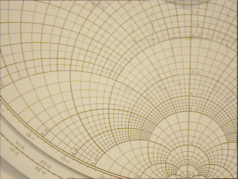
A number of scales are provided on the calculator to perform useful transmission line calculations. The main scale is an impedance co-ordinate grid. The grid is engraved onto the inner circle and each point in the grid gives the resistive and (positive and negative) reactive components of the impedance as a fraction of characteristic impedance. A diameter is marked with the resistance scale, which ranges from 0-50. The circumference of the inner circle contains the scale for reactance with two semi-circles marked from 0-50 - one for positive reactance and the other for negative reactance.
The outer circle has two scales around its circumference. These scales are marked from 0-0.50 and measure wavelengths toward the load and wavelengths toward the generator. The radial arm has a central cross-wire running down its length and eight parallel scales arranged either side of the cross-wire. The cross-wire, in conjunction with the slider cross-wire, acts as a crosshair for plotting impedances on the inner circle. The slider cross-wire also intersects the other radial arm scales. These scales are divided into two groups with four scales devoted to measurement of Voltage or Current Standing Wave Ratio (SWR) and four scales for measurements of Attenuation.
The Radio Transmission Line Calculator is capable of plotting quantities in four major groups of parameters:
1. Impedance or Admittance - Reflection coefficient magnitude and angle (in degrees)
2. Length of Line between any two points (wavelengths)
3. Attenuation between any two points (decibels) - Standing wave loss coefficient and Reflection loss (decibels)
4. Voltage or Current SWR (decibels) - Limits of Voltage and Current due to standing waves.
The particular calculator in possession of this Museum was originally manufactured for use in the Directorate of Airways, Department of Civil Aviation, the Commonwealth of Australia. The calculator was used in the Physics Department during a period of extensive radio and ionospheric research in which a number of antenna arrays were constructed and transmission lines assembled. The calculator shows signs of extensive use with pencilled calculations still evident on the face of the calculator. Two references are mentioned in the instructions printed on the rear of the calculator. These references are articles written by the designer of the calculator, Phillip H. Smith. The calculator was designed in the Radio Development Department of Bell Telephone Laboratories, New York City. The articles describe, in detail, the use of the calculator for all the calculations it can perform. Also, details of construction of a similar calculator are given.
DW